Pages

Showing posts with label aeromodelismo. Show all posts

Sunday, 11 May 2014

Sistema integrado para FPV con pantalla LCD de 7" y estructura 3D-printed - 1a entrega

Integrated FPV system with 7" LCD screen and 3D-printed frame - 1st delivery


Hace ya un tiempo que compre los componentes para poder montar un FPV con los aeromodelos que tengo, o un hipotético renacimiento del quadcopter en el futuro, pero por falta de tiempo, otros proyectos y la falta de una pantalla o unas gafas FPV (googles) había dejado el proyecto en stand-by hasta ahora.
It's been a while that I've bought some components for building up my FPV system to be mounted in my planes or a future re-born of the quadcopter but due to a lack of time, other projects and the missing screen or googles to view the transmission the project was in stand-by.

El problema era que no estaba seguro de invertir 300€ en los googles sin tener claro si luego realmente les iba a sacar partido, así que me decidí por comprar una pantalla LCD de 7" en ebay que me costó menos de 40€ incluyendo la placa controladora con entrada para AV, VGA y HDMI.
As I was not sure if investing almost 300€ in the googles was going to make sense, I just decided to go for a 7" LCD screen that I've bougth in ebay for less than 40€, including the controller board (with AV, VGA and HDMI inputs).

Pero lo siguiente era poner todos los componentes juntos, así que diseñé un pequeño marco para imprimirlo con la impresora 3D que me sirviera para acomodar los componentes de una manera compacta, y en un futuro tal vez poder montar el conjunto sobre la radio RC o en un trípode.
But now I needed to put everything together, so I designed a 3D-printed frame to arrange the componentes with the idea of keeping the system compact (and maybe later on mount this directly on top of the RC radio).


Thursday, 14 November 2013

Porqué puede ser interesante prestarle atención a "Teoría de Control" en la Universidad

Why could be interesting paying attention to "Theory of Control" at the University

Si me hubieran mostrado este video antes de cursar "Teoria de Control" en la facu, seguramente que le hubiera presetado 100 veces mas atención que la que le presté... lo único que me acuerdo es que el libro era de tapa azul, y que había mucho Lagrange por ahí (Ingeniería de Control Moderna, Katsuhiko Ogata).

If I would have been invited to see this video before taking "Theory of Control" at the University, I'm sure that I was going to pay 100 times more attention that what I did... the only thing that I remember is that we used a blue book, and that there was a lot of lagrange in there (Modern Control Engineering, Katsuhiko Ogata).


El video tras el salto / The video inside...


Monday, 30 September 2013

Mi homenaje a la revista Lúpin

My tribute to Lúpin magazine


Si sos de Argentina (y si, lo escribo en "argentino", mis disculpas a los lectores del resto de hispanoamérica) y tenés mas de, digamos, 20 años, seguramente que habrás visto, leído y disfrutado de la revista mas educativa, cautivante y exitante jamás creada para los chicos. la revista Lúpin. Este es mi pequeño homenaje a la revista que me acompañó durante mi infancia y me cambió la vida. Hoy soy ingeniero aeronáutico gracias en parte a esta revista.

If you are from Argentina and you have more than, let's say, 20 years old, you've probably seen/red/enjoyed the most educative, gripping and exciting montlhy magazine create for kids: the Lúpin magazine. This is my little tribut to this fantastic magazine that was my partner during my childhood and literally changed my life: I am an aeronautical engineer thanks, in part, to this magazine.


Sunday, 26 August 2012

SLOW FLYER - Parte 5 - Bisagras (charnelas)

SLOW FLYER - Part 5 - Hinges

Para no elevar el costo y el peso de nuestro slow flyer, y para simplificar el montaje, les muestro en las siguientes fotos cómo hacer unas bisagras (charnelas) caseras. Se trata de utilizar "cinta bebé" o cinta de costura o mercería (la que se usa para hacer moños), pegandola a la superficie fija y entrecruzandola con la móvil, según se ve en las fotos. De esta forma se garantiza un giro libre y además se mantiene la posición.
In order to keep the cost and the weight of the slow flyer low, and to simplify the assembly process, in the following pictures you will find a method to create your own hinges. The basis of the process is to create the hinges using a thin fabric, like the one found in haberdasheries also known as baby tape (at least in Spanish!). The pictures show how the tape must be crossed from one side to the other, to guarantee a free movement and to keep the position.


Obviamente no estoy inventando nada nuevo; los aeromodelistas llevan décadas usando este sistema con excelentes resultados. Eso si, hay que tener cuidado de que pegar correctamente el material, ya que de lo contrario podría despegarse en vuelo y las consecuencias podrían ser catastróficas...
Obviously I'm not inventing anything; aeromodellers have used this method for decades with excelent results. Of course, you should be careful and do a good bonding of the material; if not, the tape can de-attach during flight with catastrophic results...

Finalmente, les dejo un par de fotos mas del avance constructivo. No he podido hacer mucho en estos días, pero algo avanza. Ahora mismo estoy a la espera de unos TIP35 para usar la fuente de PC como fuente para el cortador de foam. No la puedo usar tal cuál está porque tiene una protección contra cortocircuitos que hace que al conectar el cortador se corte la tensión. Así pues, voy a poner un par de TIP35 en paralelo a la salida de la fuente para "engañar" a la protección. Los detalles en otro post.
Finally I leave here some pictures more of the advance of the construction. I was not able to do so much in these days. Right now I'm waiting to receive some TIP35 transistors to use the PC Power Supply as a source for the foam cutter. I can't use the power supply as it is right now because it has a short-cirtuit protection, which I'm planning to fool with the TIP35. But this will come in another post.


Friday, 10 August 2012

SLOW FLYER - Parte 4 - Diseño y construccion

SLOW FLYER - Part 4 - Design and construction

DISEÑO GEOMETRICO (3D CAD)
GEOMETRICAL DESIGN (3D CAD)

A continuación les dejo unas fotos del modelo 3D CAD y los planos 2D en escala 1:1 para que puedan fabricarlo si están interesados, aunque les aconsejo esperar a mis comentarios luego de las pruebas de vuelo. En estos momentos, el fuselaje está terminado y tengo que fabricar el ala.
Following I show you some pictures of the 3D CAD model and the 2D drawings in 1:1 scale for those who are interested in build your own. However, I suggest you wait until I post my comments after flight tests. At this very moment, the fuselage is finished and I need to build the wing.


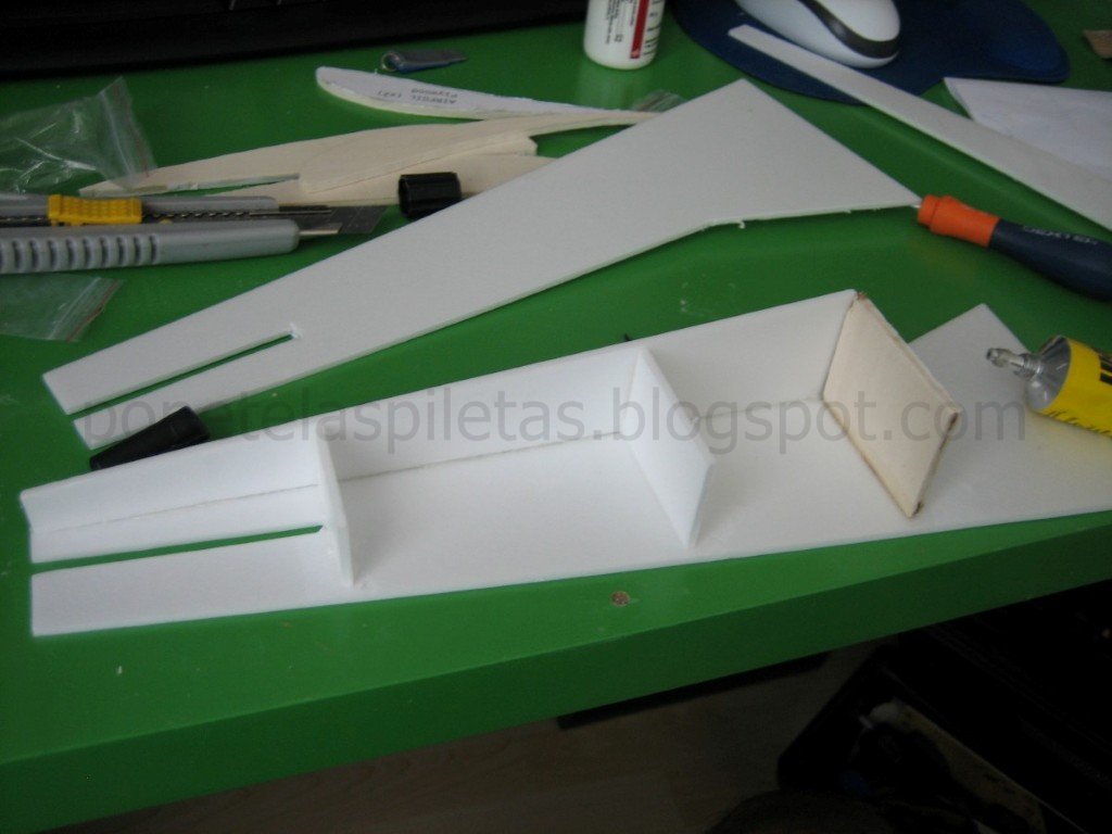
No hay trucos o técnicas especiales que contar respecto de la construcción. El material de los paneles del fuselaje son de Selitron (3 mm) como así también algunas cuadernas y el empenaje vertical y horizontal (aunque en 2 planchas de 3mm). Los refuerzos de madera son de terciada o contrachapado (4,3 mm), aunque realizando algunas mejoras en el diseño se podría fabricar íntegramente en Selitron, ya que he notado que este material cuando se usa en estructura cerradas tipo cajón es bastante resistente y se pueden realizar estructuras bastante estables.
There are no tricks or special things to comment regarding building techniques. Skin fuselage material is Selitron (3 mm) as well as some frames and horizontal and vertical tail plane (2x3mm). Reiforcements (wooden skeleton) is done with plywood (4,3 mm), however, with some improvements on the design, I realized that the plywood might not be needed as the Selitron used in closed boxes structures is giving enough strength and stability.

La madera la corté con un tornito Dremel, aunque lo ideal es hacerlo con una sierra de calar y luego retocar con el Dremel. El Selitron se corta con un cutter. Para pegar el Selitron usé UHU Por (UHU para polyestireno), para pegar la madera usé cola de madera PATTEX Holz y para pegar el Selitron a la madera utilicé un pegamento chino que no se cómo se llama pero lo tengo de un viejo Cessna chino que destrocé en su 2do vuelo hace un par de años.
I cutted the wood with a Dremel tool, but the ideal thing is to do it with a keyhole saw and afterwards finish it with the Dremel. The Selitron can be cutted with a cutter. To glue the Selitron I used UHU Por (UHU for polystyrene); to glue the plywood I used normal PATTEX glue for wood and to glue the Selitron to the wood I used a chinese glue that I don't know the name, but I have it from an old chinese Cessna that I crashed in its 2nd flight a couple of years ago.


Sunday, 29 July 2012

SLOW FLYER - Parte 3 - Diseño y construccion

SLOW FLYER - Part 3 - Design and construction


Luego de darle vueltas al diseño que estoy realizando en CAD (ya les mostrare el avance en otro post), he cambiado de parecer en cuanto a utilizar una placa curva como perfil aerodinámico del ala. El motivo del cambio es puramente estructural; no creo que el material del que dispongo pueda ser suficientemente rígido para ser usado en solitario, sin el agregado de largueros, cosa que no sería factible desde el punto de vista aerodinámico. Así pues, en este post les muestro la selección del perfil. 
After thinking about the design and seeing the advance in the CAD 3D that I'm doing (I'll you you some pictures soon), I changed my mind regarding the use of the curved panel as airfoil for the wing. The reason is purely related to structural strength; I don't believe that the material that I have will be strong enough to handle the loads without the addition of spars, which won't be possible from the aerodynamic point of view if I use a curved panel as airfoil. Therefore, this post is to show the selection of the airfoil.


CALCULO DEL NUMERO DE REYNOLDS 
REYNOLDS NUMBER CALCULATION

Primeramente vamos a calcular el numero de Reynolds que será de utilidad al trabajar con las curvas de los perfiles.
Let's calculate the Reynolds number that will be useful when we need to work with the airfoils' data.


La forma mas rápida y mas precisa es usar la calculadora de Reynolds de la NASA: 
The most quick and accurate way is to use the NASA Reynolds calculator:


Nuestros datos
Our data

rho = 1,16 kg/m3 (500m altitude)
V = 10 km/h = 2,7 m/s
D = 0,85 m (wingspan) 
mu = 1.718E-5 N.s/m2 (not necessary in the calculator) 

Re = 155981


SELECCIÓN DEL PERFIL ALAR
SELECTION OF THE AIRFOIL

La premisa para la selección del perfil alar es tener el mayor CLmax posible para nuestro número de Reynolds, sin importar el Cd (incluso, a mayor Cd mejor para tener menor velocidad). Para ello solo basta buscar en internet y encontraremos cientos de sitios con información. En mi caso particular, he buscado a través de la palabra clave "perfil alar baja velocidad" (en inglés) y he dado con muchos sitios, incluso con uno que visitaba mucho cuando estudiaba en la universidad allá por el año 2000. Me refiero a la base de datos de perfiles de la Universidad de Illinois.
The input for the selection of the airfoil for our slow flyer is, as mentioned before, to search for the profile with the higher CLmax for our Reynolds, despite its Cd (moreover, the bigger the Cd, the lower the speed).For this you can use Google and you will find thousands of websites with information. I searched using the keywords "airfoil low speed" and I was almost directly redirected to one website that I used to visit a lot when I was in the university down there in 2000... I'm talking about the airfoil database of the University of Illinois.

Mi búsqueda terminó en el S1223, un perfil de gran combadura y muy alto CLmax para nuestro Reynolds. He utilizado la información de ESTE DOCUMENTO, pero también he utilizado el programa JAVAFOIL con el cuál he obtenido la curva CL vs alfa exacta para el Reynolds calculado.
My search ended in the S1223, which has a very high camber and a very high CLmax for the estimated Reynolds. I've used the information from THIS DOCUMENT, but I also used the aplication called JAVAFOIL for getting the precise CL vs alpha slope for the estimated Reynolds.


---- Este post se actualizará en breve ----
---- To be updated soon ----

Saturday, 28 July 2012

Cálculo de la velocidad de pérdida - Applet

Stall speed calculation - Applet.

Encontré un lindo applet en este link para el cálculo de la velocidad de pérdida. Es bastante rápido de usar y de buena ayuda para los que sean algo negados con los números, ya que hace los cambios de unidades y además introduce la posibilidad de utilizar un ala trapezoidal.
I've found a nice applet in this link for the calculation of the stall speed. It's quite fast and helpful for those who don't like number as it's automatically changing units and also giving the possibility of introducing wing taper.

La única pega que le encuentro es que usa una aproximación para calcular la velocidad de pérdida, que aunque es mas conservativa, hace alguna suposición que tal vez no sea adecuada para todas las condiciones. De cualquier forma, se puede cambiar fácilmente en el texto del script (bastante simple de seguir).
The only negative point that I see is that is using an approximation to calculate the stall speed. Even though is a little bit more conservative, it's taking an assumption that perhaps is not accurate for all conditions. In any case, it can be easily change in the script text.

-->

Calculate Wing Loading, Area & Stall Speed
Wingspan: inches
mm
Wing Root Chord: inches
mm
Wing Tip Chord: inches
mm
Or the Average Chord: inches
mm
Or the Wing Area: sq.in
sq.dm
Model Weight: ounces
grams
Max Lift Coefficient:
WING LOADING: oz/sq.ft
g/sq.dm
CUBIC LOADING: oz/cu.ft.
STALL SPEED: mph
Km/h

Friday, 27 July 2012

SLOW FLYER - Parte 2 - Diseño y construcción

SLOW FLYER - Part 2 - Design and construction


Antes de continuar con nuestro diseño, les sugiero que lean el artículo de este LINK que les dará una introducción mas detallada de la diferencia entre un Slow Flyer y un Park Flyer, como así también una buena explicación de porqué los Slow Flyers vuelan lento. Además pueden visitar el resto del sitio, que es mas que interesante.
Before continuing with our design, I would suggest you read the article in the following LINK, which will give you a nice and more detailed introduction to the differences between a Slow Flyer and a Park Flyer, as well as a brief explanation of why the Slow Flyers actually flight slow. Moreover, I invite you to visit the rest of the website; it's really interesting.


DETALLES CONSTRUCTIVOS
CONSTRUCTIVE DETAILS

Para la realización del modelo no he tenido muchas opciones, ya que el material que puedo conseguir en mi zona es limitado, y sino tengo que pedirlo por correo incrementando el costo y corriendo el riesgo que el material pedido no se ajuste a lo que busco.
For the construction of the model I had not so many options, as the material that I can obtain in my area is limited, and otherwise I should request it via mail, increasing cost and taking the risk of requesting a material that is not fitting to what I'm looking for.

Así pues, en el Baumax he conseguido un material que se llama Selitron, de la firma Selit, que tiene pinta de ser un Depron pero con otro nombre (aunque no estoy seguro porque el Depron solo lo he visto en fotos). Este material se parece mucho (si es que no es el mismo) al utilizado en las bandejas en las que viene la carne en algunos supermercados. Lo conseguí en un paquete que trae varias láminas de 3mm de espesor, de 80 x 62 cm, haciendo un total de 5 m2, por un costo de alrededor de 12€. Con esto tengo material para hacer muchos aeromodelos.
So I went to my local Baumax and I found a material called Selitron, from Selit, that looks like a Depron but with a different name (I'm guessing, because I've never seen Depron live in my life). This material looks a lot (if it's not the same) to those from the meal trays from supermarket. I found it in a package containing several plies of 3mm thickness,and 80 x 62 cm, completing 5 m2 for a cost of around 12€. With this I have enough material for several models.


La fabricación se complementará con terciada de 4mm (contrachapado) que me sobró del quadcopter, además de pegamentos para poliestireno, un tren de aterrizaje de un aeromodelo viejo, etc.
The construction will be complemented with 4mm plywood, the same used for the quadcopter, as well as glue for polystyrene, an old landing gear from other model, etc.


SELECCION DEL PERFIL ALAR Y ESTIMACION DE LA VELOCIDAD DE PERDIDA
SELECTION OF AIRFOIL AND ESTIMATION OF STALL SPEED

Lo que queremos es un avión que vuele lento, y si analizamos los modelos similares veremos que parte de esa poca velocidad y gran sustentación se debe al uso de perfiles alares curvos (placa curva, perfil sin intradós), que generan una gran sustentación a poco que se varíe el ángulo de ataque, y a la vez un gran arrastre (drag), que merma la velocidad de avance.
We want an airplane that flights slowly, so we take a look at the similar models and we will see that small speeds, high lift and cheap construction is normally associated to curved airfoils uncercambered (curved plates); these generate good lift with small increments of angle of attack and at the same time a great amount drag, which is helping to reduce the flight speed.

No obstante este analisis preliminar, no descartaremos la posibilidad de realizar un ala con un perfil cerrado, utilizando algún otro material o método constructivo. De hecho, dispongo de un buen panel de poliestireno expandido de 6 cm de espesor con el que poder fabricar un ala cerrada utilizando el método de los perfiles de puntera y el cortador de hilo caliente.Nevertheless this preliminary assumption, let's not discard definitely the idea of building a wing with a closed airfoil, using other material or constructive method. In fact, I have a very nice 6cm thick polystyrene panel ready to be used for a closed wing using the method of the tip profiles and hot wire cutter.

Para saber cuán lento puede volar nuestro avión tenemos que realizar una estimación de la velocidad de pérdida (Vstall), pero para ello necesitamos datos relacionados con el perfil alar que utilzaremos (coeficiente de sustentación máximo antes de la pérdida, CLmax) o la carga alar, la cuál tenemos de referencia en la tabla de aviones similares de la entrega anterior.
To know how slow can our airmodel flight, we should estimate the stall speed (Vstall). To do so, we will need some data from the selected airfoil (lift coeficient at stall speed, CLmax) or the wing loading, which we have some references from the table of similar models presented in the previous post.


Para obtener datos del perfil alar hay muchos sitios web donde encontrar información, incluso gente que diseña sus propios perfiles y cuelga la información en internet. En mi caso, y dado que voy a utilizar una placa curva, he preferido utilizar el applet FOILSIM III de la NASA, que es bastante práctico porque en su última versión permite introducir datos referentes al ala.
There are a lot of websites from where you can find information about airfoils, and also people designing their own airfoils and sharing the information on the web. In the case of my curved plate, I preferred to used the NASA applet called FOILSIM in its version III, which is quite interesting to use and it also allows you to put information of the wing.

En FoilSim seleccionamos "Curve Plate", y luego introducimos los parámetros de geometría estimados en "Shape" (alfa = 2º, Camber = 10%), para finalmente ir a "Select Plot" y plotear Cl vs Angle de donde podremos obtener el CLmax de nuestro perfil (cima de la curva) jugando con el ángulo de ataque. En el caso de mi perfil, el CLmax = 2,1 y se obtiene alfa = 13,96º.
In FoilSim select "Curve Plate" as airfoil, introduce the parameters of the desired geometry by clicking "Shape" button (in my case alfa = 2º and Camber = 10%) and finally go to "Select Plot" and plot Cl vs Angle, and you will be able to obtain the CLmax of the profile (top of the slope). For my airfoil, CLmax = 2,1 for an angle of attack alfa = 13,28º.


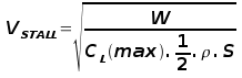
Procederemos ahora a calcular la velocidad de pérdida mediante la ecuación que les muestro a continuación. 
We proceed to calcule the Vstall with the equation that you can find below. 

 donde / where
W = peso del avión / model weight
rho = densidad del aire / air density = 1,18 kg/m3 (sea level & 25ºC)
S = superficie alar / wing surface

de la entrega anterior / from previous delivery
W = 0,250 kg
S = 0,17 m2  

entonces / then
Vstall = 1,09 m/s = 3,92 km/h 

Este dato resulta demasiado optimista y seguramente nuestra Vstall será mayor. Además, estamos idealizando el ala a partir del perfil (lo que se conoce como "ala infinita"). Como no lo sabemos a ciencia cierta (incluso aunque tuviésemos el avión volando sería difícil de medir), para tener mas información vamos a ver cómo influye W en la Vstall (solo me refiero a W porque S lo dejamos "congelado" por definición geométrica del ala).
This value results quite optimistic for me, and I'm sure that the real Vstall will be higher. In addition, we are idealizing the wing from the airfoil (also known as "infinite wing"). As we won't know precisely what is going to happen (even having the airplane flying will be difficult to measure), let's study the influence of W on that Vstall to have a better understanding (I'm only referring to W because S is frozen by geometrical definition of the wing).

Sunday, 22 July 2012

SLOW FLYER - Parte 1 - Diseño y construcción

SLOW FLYER - Part 1 - Design and construction

25/07/2012  -->  Editado: agregada carga alar  /   Edited: added wing loading

En esta serie de posts trataré de comentar mi primer experiencia en el diseño de un aeromodelo, para lo cuál he elegido realizar un modelo que tenga una velocidad de vuelo reducida, para así poder disfrutar de las maniobras.
In these posts I'll try to comment my first experience designing an airmodel, and for the first design I've selected a type of model that has a slow flight speed, that will give me the possibility of enjoy every maneuver during flight.


DEFINICION DE LOS PARAMETROS DE DISEÑO
DESIGN PARAMETERS DEFINITION

Pero, ¿cómo comenzar? Al igual que como hemos hecho con el quadcopter, vamos a proceder a buscar información de otros slow flyers y así tener referencias, tratando de prestar atención al motor utilizado (KV y potencia instalada), tamaño de la hélice, envergadura, superficie alar, materiales, y finalmente, el resto de dimensiones generales.
But, where to start? As we did with the quadcopter, we will start by collecting information of other slow flyers in order to have references, trying to pay particular attention to the motor (KV and installed power), propeller size, wingspan, wing surface, materials, and the remaining dimensions.

La siguiente tabla muestra algunos aeromodelos que pueden ser tomados como referencia.
The following table shows some airmodels that can be taken as a reference. 


De la tabla se pueden sacar las siguientes conclusiones preliminares:
From the table, the following preliminary conclusions can be made:

Motor: brushed or brushless
Propeller: 6 to 8 "
Wingspan: ~ 0,85 m
Wingarea: ~ 0,17 m2 
Target weight: ~ 0,250kg (conservative)
Wing loading: 1,47 kg/m2
 

Estos serán nuestros parámetros preliminares de diseño, y nos sirven para acotar el espectro de estudio. De esta tabla nos está faltando el empuje real en la hélice, que será determinante para poder dimensionar el modelo, pero ya les he mostrado en este post como realizar una medición de empuje el empuje.
These will be our preliminary design parameters, and will give us the boundaries for our study. From this table we are missing the propeller thrust, which we will need for the dimensioning. However, I've already shown you in this thread how to measure the thrust on a propeller.

Finalmente, les dejo unas fotos de los aeromodelos referenciados para que puedan hacerse una idea de las diferentes configuraciones. En la próxima entrega comenzaremos con los cálculos para diseñar nuestro slow flyer.
Finally, I leave you some pictures of the referenced airmodels for a better understanding of the different configurations. In the next delivery we'll start with the calculations to design our own slow flyer.


 ElectriFly FlyLite


 HobbyZone Mini Super Cub


Night Vapor


GWS Pico Stick


StevensAero Quick Oats 250


E-Flite Jenny JN-4


ElectriFly Tiger Moth

Monday, 9 July 2012

Primer vuelo "controlado" del EasyStar

EasyStar first "controlled" flight

Mucha suerte tuve el domingo pasado tratando de volar este engendro llamado EasyStar. Era la cuarta vez que salía al campo con el avión y no había podido hacerlo volar controladamente nunca. La primera vez por culpa de las baterías, luego por culpa del motor brushed que viene de serie que no mueve ni una pluma, luego por la falta de balanceo y el mal (o nulo) trimado...
I was very lucky this last Sunday trying to fly this little spawn called EasyStar. It was the fourth time that I was in the country trying to make a controlled flight without success. The first time the problem were the batteries, then the original motor (powerless), then the unbalance and/or a bad trimming, etc...

El primer vuelo del domingo casi termina en catastrofe, pero de las gordas. No solo casi lo choco contra unos cables de alta tensión (que estaban como a 200 metros), sino que luego para tratar de que perdiera altura se me fue entre unos árboles y unas casas... Si ven por donde pasó y cómo salió ileso no lo podrían creer, mas siendo que yo estaba a 200 m tapado por árboles, o sea, visibilidad nula. Imagínense un cuadrado de 10x10 metros, con casas de un lado, árboles de otro, y cables de alta tensión por arriba... bueno, justo por ahí se metió el bicho, sin control, cruzó una calle y aterrizó solito del otro lado, en un cesped, casi sin golpearse, teniendo otra casa con garage y autos a solo 4 metros a su izquierda. Todo a ciegas. Fuimos a buscarlo y ya me imaginaba lo peor, metido adentro de una casa por una ventana, o peor, rompiendo las placas solares de los techos que tanto abundan por aquí... tendría que haber sacado una foto para guardarla de recuerdo.
The first flight of this Sunday almost end in a catastrophe. Not only that I almost crashed it into a high tension electrified lines (which were like 200 meters from were I was), but also that after trying to reduce altitude, I lost it behind some trees. You wouldn't believe how it did to survive seeing where it flew through. Imagine a 10x10 m window, with a house on one side, trees on the other and the high-tension lines on top... yes, just there... totally uncommanded as I was not touching the radio... Moreover, it crossed the street to land (it was untouched) in a small green garden on the other side, with another house 4 meters on its left and a garage with cars. All alone, uncontrolled. I was expecting the worst, broken windows, crashing to a solar panel in a roof... but not, it was there, just landed in the garden... It's a shame that I have no picture of the situation...

Con la moral baja y con los nervios que no dejaban el cuerpo, nos fuimos a otro campito, arriba de una colina y con mucho espacio libre por delante para probar de nuevo... y finalmente el muy jodido voló... y voló bien y por un buen rato... para mejor muestra, los videos...
Hopeless and still nervous, we moved to a different field on top of a hill, more spacious but a little bit windy... and finally, being the 5th attempt, the spawn flew... and it flew nice and for several minutes... see the videos below.

Las claves del "éxito" del vuelo fueron, primeramente, un par de horas que le metí al simulador que compré por ebay (si son principiantes, no duden un minuto en comprar un simulador, es verdaderamente fundamental), y en segundo lugaro, corregir una tendencia a virar a derecha que había detectado en el vuelo casi-catastrófico con un poquito de trimado del rudder.
The clues for the success were some hours spent in a cheap simulator bought in ebay, and in a second place, the correction in the yaw that I've detected in the quasi-catastrophic flight, by trimming a little bit the rudder. If you are beginners, you must definitely do some practice with a simulator, is mandatory...


Saturday, 7 July 2012

MEDICION DE EMPUJE DE HELICES

PROPELLER THRUST MEASUREMENT

En este post les traigo una información que puede resultar valiosa y útil para los aeromodelistas. Me he tomado el trabajo de realizar una prueba de empuje de las hélices que tenía disponible y documentar los resultados en una tabla, además de tomar fotos.
In this post I bring you some data that can be useful for the aero-modellers. I've done a thrust test of the propellers that I have available at home, documenting the results in a table and taking some pictures.

Las hélices que he testeado son:
The propellers tested are:

#1 - 5x5
#2 - diam 80mm (modif)
#3 - 8x4
#4 - 8x6
#5 - 10x4,5
#6 - 12x4,5


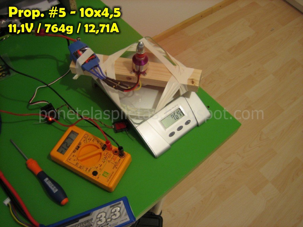
Para la realización de esta prueba he utilzado una báscula electrónica de cocina sobre la cuál he montado una madera que he utilizado de bancada para el motor. Evidentemente, las hélices se han montado de tal manera que el empuje presione la placa de la báscula (la hélice "sopla" hacia arriba).
To carry this test I've used an electronic bascule (those for cooking), in which I've located a piece of wood to give support to the motor. Obviusly, the propellers have been attached in such a way that the thrust generates a pressure on the bascule plate (the propeller blows air upwards).

De momento solo he realizado la prueba utilizando un motor brushless C2830 KV1000 (el que tengo en el quadcopter). Sin embargo, he tomado mediciones utilizando dos tensiones de alimentación diferente: 7,2 y 11,1 Volts (baterias Lipo de 2 y 3 celdas). Si me agarran ganas y tengo tiempo, realizaré la misma prueba pero con otro motor (CF2805-14 KV2840).
By the moment I've done the test using only one motor, a brushless C2830 KV1000 (the one that I'm using in the quadcopter). However, I've taken measurements using two different input voltages: 7,2 and 11,1 Volts (Lipo batteries of 2 and 3 cells). If I feel like and got some time, I'll redo the test for another motor that I have (a CF2805-14 KV2840).

En el montaje del "banco de pruebas" he incluido un multímetro (como amperímetro) para tener la medición de corriente consumida. Todos las hélices se probaron con la misma configuración de motor, esc (60A) y trimado de radio. La balanza fue puesta a cero cada vez antes de iniciar un nuevo test.
In the set-up of the "test bench" I included a multimeter (used as amperimeter) to get the current consumption. All the propellers were tested using the same configuration of motor, esc (60A), and radio trimming. The bascule was set to zero every time before starting a new run.

A continuación les dejo todas las fotos y al final las tablas y unas curvas para representar gráficamente los resultados obtenidos.
I leave you here the pictures and a table with the data collected, as well as some graphs showing the tendences.