QUADCOPTER - Final delivery
Se podría decir que mi historia con los quadcopters tiene un final agridulce.
I can say that my story with quadcopters has a bittersweet end.
Desde el punto de vista técnico, he sido capaz de diseñar y construir dos quads differentes, usando dos configuraciones (+ & x), dos materiales principales diversos para el cuadro (madera y aluminio), he podido probar dos placas controladoras (HK v1.1 y HK KK2.0), actualizar el firmware de las controladoras, aprendí cómo setear los ESC con el recorrido del stick de la radio e investigar respuestas de vuelo usando 4 medidas diferentes de hélices (6", 8", 10" y 12"). Más aún, he podido resolver problemas de estabilidad (causados por la mala configuración de los ESC) y he conseguido al final un quad bastante estable. Todo esto puede considerarse la parte "feliz" de la historia.
From the technical point of view, I was able to design and build two quads in two different configurations (+ & x), using two different basic materials (wood & aluminium profiles), try two different controllers (HK v1.1 and HK KK2.0), introduce new firmware to the controllers, lern to adjust the ESC and investigate flight behaviors using 4 different propeller sizes (6", 8", 10" and 12"). Even more, I solve stability problems (due to the ESCs not properly regulated), and I was able to get a pretty stable quad at the very end of the process. This can be considered the sweet part of the story.
La parte no tan felíz, o mas bien "amarga" comienza con mi último vuelo realizado, que puede pasar a convertirse en mi "último" vuelo. Una vez conseguido un buen quad, estable y manejable, sale a la superficie el hecho de que soy muy malo volando estos bichos endemoniados. No he sido capaz de realizar un vuelo normalito, y casi que pierdo el quad, debiendo de cortar motor con el quad como a 30m de altura porque sino lo perdía de vista, con la consequente caída en picada y el aporrizaje... (otras) dos hélices a la basura y un brazo del quad de aluminio todo doblado fue el saldo de la catástrofe.
The bitter part of the story starts with my last flight, which I consider probably my final flight. Now that I have a pretty stable quad, it comes to the scene the fact that I'm awful flying this damned things. I was not able to do a normal flight test and I almost lost the quad, needing to cut it off and make it fall before loosing it from sight, with the consequent hard landing, two (more) propellers broken and one aluminium arm bended...
Así pues, este post es para declarme oficialmente como un queso volando quads, y hasta que no consiga un simulador o que mi hijo sea suficientemente grande para volarlo él solito, yo no pienso volver a volar quads. Prefiero usar mi poco tiempo disponible para centrarme en los aviones que son mucho mas amigables para el piloto principiante, hacer mis primeros pasos en FPV y dedicarme a algunos proyectos que tengo en mente.
So, this post is to officily declare to the world that I suck as a quadcopter pilot, and until I get a flight simulator or my kid becomes old enough for him to flight, I won't see myself trying again. I'd rather expend my little time in the airplanes that are more flight-friendly, the FPV and my upcoming new projects.
¡Pero que mi historia no les desanime! Fabricar los quads es divertido, y quien dice, tal vez uds resultan mucho mejor piloto que yo y terminan disfrutando.
But please don't think in quitting if you are starting!... Perhaps you are better pilots than me!!
¡Buenos vuelos!
Good flights!
Showing posts with label esc. Show all posts
Showing posts with label esc. Show all posts
Monday, 7 January 2013

Monday, 3 December 2012
QUADCOPTER - 7ma Entrega - Calibración de los ESC
QUADCOPTER - 7th Delivery - ESC Calibration

Para calibrar los ESC (controladores de los motores eléctricos) hay que conectarlos uno a uno al receptor de la radio y realizar la siguiente secuencia:
To calibrate the ESC you need to connect them one by one to the RC receiver and follow the next steps:
1) conectar el ESC al receptor, manteniendo el transmisor apagado
1) connect the ESC to the receiver, keeping the transmitter turned off
2) conectar la batería al ESC
2) connect the battery to the ESC
3) mover el stick del thrust (power del motor) a tope
3) move the thrust stick to the maximum position in the transmitter
4) encender el transmisor
4) turn on the transmitter
5) luego de escuchar dos "beep" provenientes del motor, bajar el stick a 0
5) you will hear two short "beeps" coming from the motor, after this, put the thrust stick to 0
6) se escucharán dos "beep" cortos y uno largo, confirmando que el ESC ha quedado calibrado para el recorrido de la radio.
6) then you will hear 2 short "beeps" followed by a longer one, which are confirming that the ESC is now calibrated for the thrust stick of our RC transmitter.
Es importante prestar atención antes de realizar la calibración de que en caso de contar con un transmisor con programación, los recorridos de los sticks estén al 100%. De lo contrario el ESC se calibrará al recorrido del setup del transmisor y no al real.
Please pay attention in those programmable radios to have the path of the sticks in 100%, otherwise the ESC will be calibrated to the set path and not to the total path.
Para calibrar los ESC (controladores de los motores eléctricos) hay que conectarlos uno a uno al receptor de la radio y realizar la siguiente secuencia:
To calibrate the ESC you need to connect them one by one to the RC receiver and follow the next steps:
1) conectar el ESC al receptor, manteniendo el transmisor apagado
1) connect the ESC to the receiver, keeping the transmitter turned off
2) conectar la batería al ESC
2) connect the battery to the ESC
3) mover el stick del thrust (power del motor) a tope
3) move the thrust stick to the maximum position in the transmitter
4) encender el transmisor
4) turn on the transmitter
5) luego de escuchar dos "beep" provenientes del motor, bajar el stick a 0
5) you will hear two short "beeps" coming from the motor, after this, put the thrust stick to 0
6) se escucharán dos "beep" cortos y uno largo, confirmando que el ESC ha quedado calibrado para el recorrido de la radio.
6) then you will hear 2 short "beeps" followed by a longer one, which are confirming that the ESC is now calibrated for the thrust stick of our RC transmitter.
Es importante prestar atención antes de realizar la calibración de que en caso de contar con un transmisor con programación, los recorridos de los sticks estén al 100%. De lo contrario el ESC se calibrará al recorrido del setup del transmisor y no al real.
Please pay attention in those programmable radios to have the path of the sticks in 100%, otherwise the ESC will be calibrated to the set path and not to the total path.
Sunday, 2 December 2012
QUADCOPTER - 6ta Entrega - Evolución
QUADCOPTER - 6th Delivery - Evolution
Llevo tiempo sin postear por razones familiares, pero acá estoy nuevamente para dejarles algunos comentarios e impresiones luego de varias pruebas con el quadcopter. Mucho ha llovido desde mi último post relacionado al quad...
It's been such a long time since my last post and due to familiar reasons I was not able to keep the blog updated... but here I am again bringing you some comments and impressions after some tests and changes in the quadcopter. A lot have happened in this time...
It's been such a long time since my last post and due to familiar reasons I was not able to keep the blog updated... but here I am again bringing you some comments and impressions after some tests and changes in the quadcopter. A lot have happened in this time...

Luego de algún accidente catastrófico que demandó una revisión total, se puede decir que del quad original poco queda ya. Por la falta de experiencia asocié la inestabilidad de los primeros vuelos a la estructura de madera que había fabricado (luego comprobaría que esto no era correcto) y a la placa HobbyKing v1.1. Así que tratando de solucionar esto fabriqué un nuevo cuadro mas pequeño con brazos de aluminio y compré una placa controladora HK KK2.0
After one or two catastrophic accidents that demanded a complete revision, I can say that there is not too much remaining from the original quad. Due to the lack of experience I asociated the instability of the first flights to the wooden frame and the HobbyKing v1.1 controller (later I was going to discover that this was not right) So, trying to solve this I've done a new frame, smaller, with aluminium arms and I've bought a HK KK2.0 controller.


Pero el cuadro original de madera y la placa v1.1 tampoco parecían ser el problema. De hecho, con la nueva placa KK2.0 no pude hacer despegar el quad del suelo porque se daba vuelta. Empecé a pensar que la placa estaba mal porque todo el mundo hablaba muy bien de esta placa y yo parecía ser el único con problemas.
But the original wooden frame and the v1.1 controller seemed not to be the problem either. In fact, with the new KK2.0 controller I was not able to raise the quad from the floor as it was flipping in the first shot. I started to think that the new controller was wrong because everybody was speaking really good about it and in my case it was a desaster.
Pero finalmente luego de leer varios blogs y foros, me dí cuenta que ¡no había hecho la calibración de los ESC!. Originalmente yo pensaba que esto de la calibración estaba relacionado con algún tipo específico de ESC programable, pero luego me di cuenta que casi en la totalidad de los ESC es posible (y se debe) realizar la calibración para detectar todo el rango del stick de la radio.
But finally, after reading other blogs and forums, I realized that I haven't done the ESC calibration!... I thought that this was related to some kind of specific ESC that you can program, when I found out that in almost all the cases you can (and must) do the calibration in order to detect the whole path of the thrust stick in the radio.
Luego de realizar la calibración salí a probar el quad nuevamente y el cambio fue radical. A la primera, sin cambiar ningún parámetro de la controladora, el quad despegó con total estabilidad y el control fue mucho mas simple. Ahora me toca aprender a volarlo, porque en el 2do vuelo lo colgué de un arbol (recomendación: no volar cerca de árboles en los primeros vuelos).
After doing the calibration of the ESC I went out to test the quad and the change was radical. In the first flight, without changing any other parameter of the controller, the quad took off totally estable and the flight control was much easier than before. Now I need to learn to fly this damned thing, because in the 2nd flight the quad ended in the top of a tree (suggestion: don't flight close to trees in your first flights).
Sunday, 26 August 2012
SLOW FLYER - Parte 5 - Bisagras (charnelas)
SLOW FLYER - Part 5 - Hinges
Para no elevar el costo y el peso de nuestro slow flyer, y para simplificar el montaje, les muestro en las siguientes fotos cómo hacer unas bisagras (charnelas) caseras. Se trata de utilizar "cinta bebé" o cinta de costura o mercería (la que se usa para hacer moños), pegandola a la superficie fija y entrecruzandola con la móvil, según se ve en las fotos. De esta forma se garantiza un giro libre y además se mantiene la posición.
In order to keep the cost and the weight of the slow flyer low, and to simplify the assembly process, in the following pictures you will find a method to create your own hinges. The basis of the process is to create the hinges using a thin fabric, like the one found in haberdasheries also known as baby tape (at least in Spanish!). The pictures show how the tape must be crossed from one side to the other, to guarantee a free movement and to keep the position.


Obviamente no estoy inventando nada nuevo; los aeromodelistas llevan décadas usando este sistema con excelentes resultados. Eso si, hay que tener cuidado de que pegar correctamente el material, ya que de lo contrario podría despegarse en vuelo y las consecuencias podrían ser catastróficas...
Obviously I'm not inventing anything; aeromodellers have used this method for decades with excelent results. Of course, you should be careful and do a good bonding of the material; if not, the tape can de-attach during flight with catastrophic results...
Finalmente, les dejo un par de fotos mas del avance constructivo. No he podido hacer mucho en estos días, pero algo avanza. Ahora mismo estoy a la espera de unos TIP35 para usar la fuente de PC como fuente para el cortador de foam. No la puedo usar tal cuál está porque tiene una protección contra cortocircuitos que hace que al conectar el cortador se corte la tensión. Así pues, voy a poner un par de TIP35 en paralelo a la salida de la fuente para "engañar" a la protección. Los detalles en otro post.
Finally I leave here some pictures more of the advance of the construction. I was not able to do so much in these days. Right now I'm waiting to receive some TIP35 transistors to use the PC Power Supply as a source for the foam cutter. I can't use the power supply as it is right now because it has a short-cirtuit protection, which I'm planning to fool with the TIP35. But this will come in another post.


Friday, 10 August 2012
SLOW FLYER - Parte 4 - Diseño y construccion
SLOW FLYER - Part 4 - Design and construction
DISEÑO GEOMETRICO (3D CAD)
GEOMETRICAL DESIGN (3D CAD)
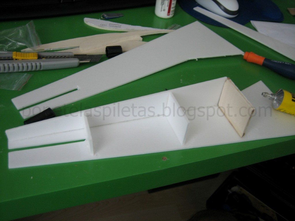
A continuación les dejo unas fotos del modelo 3D CAD y los planos 2D en escala 1:1 para que puedan fabricarlo si están interesados, aunque les aconsejo esperar a mis comentarios luego de las pruebas de vuelo. En estos momentos, el fuselaje está terminado y tengo que fabricar el ala.
Following I show you some pictures of the 3D CAD model and the 2D drawings in 1:1 scale for those who are interested in build your own. However, I suggest you wait until I post my comments after flight tests. At this very moment, the fuselage is finished and I need to build the wing.


No hay trucos o técnicas especiales que contar respecto de la construcción. El material de los paneles del fuselaje son de Selitron (3 mm) como así también algunas cuadernas y el empenaje vertical y horizontal (aunque en 2 planchas de 3mm). Los refuerzos de madera son de terciada o contrachapado (4,3 mm), aunque realizando algunas mejoras en el diseño se podría fabricar íntegramente en Selitron, ya que he notado que este material cuando se usa en estructura cerradas tipo cajón es bastante resistente y se pueden realizar estructuras bastante estables.
There are no tricks or special things to comment regarding building techniques. Skin fuselage material is Selitron (3 mm) as well as some frames and horizontal and vertical tail plane (2x3mm). Reiforcements (wooden skeleton) is done with plywood (4,3 mm), however, with some improvements on the design, I realized that the plywood might not be needed as the Selitron used in closed boxes structures is giving enough strength and stability.
La madera la corté con un tornito Dremel, aunque lo ideal es hacerlo con una sierra de calar y luego retocar con el Dremel. El Selitron se corta con un cutter. Para pegar el Selitron usé UHU Por (UHU para polyestireno), para pegar la madera usé cola de madera PATTEX Holz y para pegar el Selitron a la madera utilicé un pegamento chino que no se cómo se llama pero lo tengo de un viejo Cessna chino que destrocé en su 2do vuelo hace un par de años.
I cutted the wood with a Dremel tool, but the ideal thing is to do it with a keyhole saw and afterwards finish it with the Dremel. The Selitron can be cutted with a cutter. To glue the Selitron I used UHU Por (UHU for polystyrene); to glue the plywood I used normal PATTEX glue for wood and to glue the Selitron to the wood I used a chinese glue that I don't know the name, but I have it from an old chinese Cessna that I crashed in its 2nd flight a couple of years ago.




Sunday, 29 July 2012
SLOW FLYER - Parte 3 - Diseño y construccion
SLOW FLYER - Part 3 - Design and construction
Luego de darle vueltas al diseño que estoy realizando en CAD (ya les mostrare el avance en otro post), he cambiado de parecer en cuanto a utilizar una placa curva como perfil aerodinámico del ala. El motivo del cambio es puramente estructural; no creo que el material del que dispongo pueda ser suficientemente rígido para ser usado en solitario, sin el agregado de largueros, cosa que no sería factible desde el punto de vista aerodinámico. Así pues, en este post les muestro la selección del perfil.
After thinking about the design and seeing the advance in the CAD 3D that I'm doing (I'll you you some pictures soon), I changed my mind regarding the use of the curved panel as airfoil for the wing. The reason is purely related to structural strength; I don't believe that the material that I have will be strong enough to handle the loads without the addition of spars, which won't be possible from the aerodynamic point of view if I use a curved panel as airfoil. Therefore, this post is to show the selection of the airfoil.
CALCULO DEL NUMERO DE REYNOLDS
REYNOLDS NUMBER CALCULATION
Primeramente vamos a calcular el numero de Reynolds que será de utilidad al trabajar con las curvas de los perfiles.
Let's
calculate the Reynolds number that will be useful when we need to work
with the airfoils' data.

La forma mas rápida y mas precisa es usar la calculadora de Reynolds de la NASA:
The most quick and accurate way is to use the NASA Reynolds calculator:
Nuestros datos
Our data
rho = 1,16 kg/m3 (500m altitude)
V = 10 km/h = 2,7 m/s
D = 0,85 m (wingspan)
mu = 1.718E-5 N.s/m2 (not necessary in the calculator)
Re = 155981
SELECCIÓN DEL PERFIL ALAR
SELECTION OF THE AIRFOIL
La premisa para la selección del perfil alar es tener el mayor CLmax posible para nuestro número de Reynolds, sin importar el Cd (incluso, a mayor Cd mejor para tener menor velocidad). Para ello solo basta buscar en internet y encontraremos cientos de sitios con información. En mi caso particular, he buscado a través de la palabra clave "perfil alar baja velocidad" (en inglés) y he dado con muchos sitios, incluso con uno que visitaba mucho cuando estudiaba en la universidad allá por el año 2000. Me refiero a la base de datos de perfiles de la Universidad de Illinois.
The input for the selection of the airfoil for our slow flyer is, as mentioned before, to search for the profile with the higher CLmax for our Reynolds, despite its Cd (moreover, the bigger the Cd, the lower the speed).For this you can use Google and you will find thousands of websites with information. I searched using the keywords "airfoil low speed" and I was almost directly redirected to one website that I used to visit a lot when I was in the university down there in 2000... I'm talking about the airfoil database of the University of Illinois.
Mi búsqueda terminó en el S1223, un perfil de gran combadura y muy alto CLmax para nuestro Reynolds. He utilizado la información de ESTE DOCUMENTO, pero también he utilizado el programa JAVAFOIL con el cuál he obtenido la curva CL vs alfa exacta para el Reynolds calculado.
My search ended in the S1223, which has a very high camber and a very high CLmax for the estimated Reynolds. I've used the information from THIS DOCUMENT, but I also used the aplication called JAVAFOIL for getting the precise CL vs alpha slope for the estimated Reynolds.Mi búsqueda terminó en el S1223, un perfil de gran combadura y muy alto CLmax para nuestro Reynolds. He utilizado la información de ESTE DOCUMENTO, pero también he utilizado el programa JAVAFOIL con el cuál he obtenido la curva CL vs alfa exacta para el Reynolds calculado.


---- Este post se actualizará en breve ----
---- To be updated soon ---- Saturday, 7 July 2012
MEDICION DE EMPUJE DE HELICES
PROPELLER THRUST MEASUREMENT
En este post les traigo una información que puede resultar valiosa y útil para los aeromodelistas. Me he tomado el trabajo de realizar una prueba de empuje de las hélices que tenía disponible y documentar los resultados en una tabla, además de tomar fotos.
In this post I bring you some data that can be useful for the aero-modellers. I've done a thrust test of the propellers that I have available at home, documenting the results in a table and taking some pictures.
Las hélices que he testeado son:
The propellers tested are:
#1 - 5x5
#2 - diam 80mm (modif)
#3 - 8x4
#4 - 8x6
#5 - 10x4,5
#6 - 12x4,5

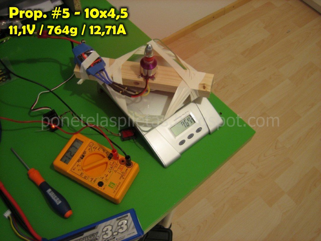
Para la realización de esta prueba he utilzado una báscula electrónica de cocina sobre la cuál he montado una madera que he utilizado de bancada para el motor. Evidentemente, las hélices se han montado de tal manera que el empuje presione la placa de la báscula (la hélice "sopla" hacia arriba).
To carry this test I've used an electronic bascule (those for cooking), in which I've located a piece of wood to give support to the motor. Obviusly, the propellers have been attached in such a way that the thrust generates a pressure on the bascule plate (the propeller blows air upwards).
De momento solo he realizado la prueba utilizando un motor brushless C2830 KV1000 (el que tengo en el quadcopter). Sin embargo, he tomado mediciones utilizando dos tensiones de alimentación diferente: 7,2 y 11,1 Volts (baterias Lipo de 2 y 3 celdas). Si me agarran ganas y tengo tiempo, realizaré la misma prueba pero con otro motor (CF2805-14 KV2840).
By the moment I've done the test using only one motor, a brushless C2830 KV1000 (the one that I'm using in the quadcopter). However, I've taken measurements using two different input voltages: 7,2 and 11,1 Volts (Lipo batteries of 2 and 3 cells). If I feel like and got some time, I'll redo the test for another motor that I have (a CF2805-14 KV2840).
En el montaje del "banco de pruebas" he incluido un multímetro (como amperímetro) para tener la medición de corriente consumida. Todos las hélices se probaron con la misma configuración de motor, esc (60A) y trimado de radio. La balanza fue puesta a cero cada vez antes de iniciar un nuevo test.
In the set-up of the "test bench" I included a multimeter (used as amperimeter) to get the current consumption. All the propellers were tested using the same configuration of motor, esc (60A), and radio trimming. The bascule was set to zero every time before starting a new run.
A continuación les dejo todas las fotos y al final las tablas y unas curvas para representar gráficamente los resultados obtenidos.
I leave you here the pictures and a table with the data collected, as well as some graphs showing the tendences.




Subscribe to:
Posts (Atom)