Pages

Showing posts with label electronics. Show all posts

Sunday, 10 May 2015

Multiple uses voltage regulator

Práctico regulador de tensión multiusos


Esto no es novedad alguna entre los "electrónicos", pero lo comparto igualmente para aquellos que no tengan tanto conocimiento de electrónica pero quieran animarse.

This project is no news for those of you more into the "electronics", but I share it anyway for those others that has not too much electronics practice and are looking for a challenge.

Lo que les traigo es un práctico regulador de tensión basado en el regulador LM317 para ser utilizado en multiples proyectos, pero yo lo he construido principalmente para poder intercalarlo entre baterías tipo Lipo de 2S, 3S o mas celdas y algún electrodoméstico que usa tensiones mas bajas (por ejemplo, una aspiradora de mano, que funcionaría con 3,7V, o sea, una lipo de 1 celda), o entre alguna fuente de mas de 18V y el cargador de Lipos IMAX B6 (que acepta hasta 18V en la entrada).
What I bring you here is a very useful voltage regulator based on the well know LM317 chip. I build this regultor with the intention of use it with Lipo batteries, so that I'm able to use big batteries with several cells with some tools or appliances normally driven by low voltage and not so life lasting NiMh batteries (like the hand-vacuum cleaners for instance). I used it as well to bring down the voltage of an adapter that I use for my IMAX B6 Lipo charger (which input voltage must be up to 18V).


También puede ser usado para reducir la tensión de la batería del coche para algún equipo que use menos tensión (como esta misma aspiradora por ejemplo).
It can be used as well in your car, to use some appliance with less than 12V (for instance, the same hand vacuum cleaner).


Sunday, 3 August 2014

Extra de vida para esa aspiradora de mano que siempre se queda corta

Giving some extra life to that hand vacuum cleaner that always dies before finishing


Estás cansado de pagar por la aspiradora en la estación de servicio? Vivís en un apartamento y no tienes conección eléctrica donde aparcas el coche? Si es así, entonces estás necesitando una aspiradora de mano urgentemente!
Are you tire of paying for the vacuum cleaner of the gas stations? Are you living in an apartment and you don't have a 220V connection close to your car? Then, you are needing a hand vacuum cleaner!

Pero si ya tenés una, sabrás que la batería de estas no suele durar mas de 3 o 4 minutos de aspiración continuada, antes de empezar a perder "chicha".. Incluso las mas caras, esas que vienen con baterías de Li-Ion, normalmente no te dan suficiente tiempo para poder aspirar a fondo el coche.
But if you already have (or had) one, you know that they have not more than 3 or 4 minutes of life before they start running out of juice... Even the expensive ones, with Li-Ion batteries, they are not giving enough time to cleane deeply a car.

Así que porqué no darle un poco de vida extra, justo esos minutos que te faltan normalmente?
So, why not adding some extra power to extend the life just those minutes more you need?


Thursday, 14 November 2013

Porqué puede ser interesante prestarle atención a "Teoría de Control" en la Universidad

Why could be interesting paying attention to "Theory of Control" at the University

Si me hubieran mostrado este video antes de cursar "Teoria de Control" en la facu, seguramente que le hubiera presetado 100 veces mas atención que la que le presté... lo único que me acuerdo es que el libro era de tapa azul, y que había mucho Lagrange por ahí (Ingeniería de Control Moderna, Katsuhiko Ogata).

If I would have been invited to see this video before taking "Theory of Control" at the University, I'm sure that I was going to pay 100 times more attention that what I did... the only thing that I remember is that we used a blue book, and that there was a lot of lagrange in there (Modern Control Engineering, Katsuhiko Ogata).


El video tras el salto / The video inside...


Friday, 11 October 2013

PRUSA i3 by diegudio - 3a Entrega - Electrónica

PRUSA i3 by diegudio - 3rd Delivery - Electronics

Una de las cosas mas importantes y tal vez mas complejas para los principiantes es lidiar con la electrónica y el firmware cuando se comienza en el mundo de las impresoras 3D. 
One of the most important things (and maybe the most "complex" for the beginners) is dealing with the electronics & the firmware when starting in the reprap 3D printing world.

En este post trataré de explicarles básicamente cuáles son los componentes electrónicos necesarios para armar una impresora 3D, por lo menos en cuanto a la estructura básica y por supuesto tomando el ejemplo de mi impresora (pueden haber otras configuraciones, claro está). Luego postearé otra nota sobre el firmware, con algo mas de detalle.
In this post I'll try to explain you in a simple way the electronics needed in a normal 3D printer like the Prusa Mendel or Prusa i3. Regarding the firmware, I'll give you a short introduction here and later I will publish a full note regarding how to deal with it.


Monday, 30 September 2013

Mi homenaje a la revista Lúpin

My tribute to Lúpin magazine


Si sos de Argentina (y si, lo escribo en "argentino", mis disculpas a los lectores del resto de hispanoamérica) y tenés mas de, digamos, 20 años, seguramente que habrás visto, leído y disfrutado de la revista mas educativa, cautivante y exitante jamás creada para los chicos. la revista Lúpin. Este es mi pequeño homenaje a la revista que me acompañó durante mi infancia y me cambió la vida. Hoy soy ingeniero aeronáutico gracias en parte a esta revista.

If you are from Argentina and you have more than, let's say, 20 years old, you've probably seen/red/enjoyed the most educative, gripping and exciting montlhy magazine create for kids: the Lúpin magazine. This is my little tribut to this fantastic magazine that was my partner during my childhood and literally changed my life: I am an aeronautical engineer thanks, in part, to this magazine.


Sunday, 24 March 2013

DIEGUDIOS - Impresora 3D - Opto endstops con HY860H

DIEGUDIOS - 3D Printer - Opto endstops with HY860H

Mucha información hay en la web y en reprap.org acerca de los "sensores de final de recorrido", endstops en inglés, y sus derivados (mecánicos, ópticos), así que no es mi intención explicar para qué sirven. Lo que aquí les traigo es información de cómo hacer sus propios opto endstops con la barrera óptica HY860H-A que se consigue por ebay a precios muy económicos (10 x 1,53€ envío incluído).
There is a lot of information in the web and reprap.org about the endstops and their derivatives (mechanicals, opticals), so it's not my intention with this post to explain why you need them. I'm just bringing you here infromation of how to do your own endstops using the optical barrier HY860H-A which is extremely cheap and you can buy 10 of these in ebay for 1,53€ including shipping.

No se olviden que este componente tiene el emisor (del foto-transistor) del lado contrario al ánodo del LED infrarrojo, por lo tanto si usan el circuito que les dejo mas abajo, tienen que tener cuidado de conectarlo adecuadamente (la masa iría cruzando el encapsulado de un lado al otro).
Notice that this opto-barrier has the emisor on the opposite side of the IR-LED anode, so in the circuit that you will see below, you need to be careful of taking the emisor properly (ground will cross from one side to the other).


Mas allá de esta particularidad constructiva, el HY 860H  se puede usar con cualquiera de los circuitos típicos que se pueden encontrar en la web. Yo prefería tener un LED como referencia visual para saber si estaba funcionando el circuito correctamente y he utilizado el diagrama que se puede ver en el blog Capolight Electronics Projects.
Besides this particularity, the HY 860H can be used with any of the tipical circuits that you can find in the web. I preferred to have a LED as a visual reference of the state of the endstop so I used the circuit presented in the blog Capolight Electronics Projects.


Se puede realizar otra disposición del LED y su resistencia para que en vez de estar normalmente encendido solamente se encienda cuando la barrera es activada. Para ello hay que colocarlo tomando su positivo del emisor del foto-transistor y conectando la resistencia a masa. El resto se mantiene igual.
You can also use a diferent set-up of the LED so instead of having it normally on it goes to "on" when the barrier is activated. For this you need to take the signal from the emisor of the photo-transistor and conect the anode of the LED there, and the cathode goes through the 560ohm resistor to ground. The rest of the circuit remains the same.

Para finalizar, les dejo las hojas de datos del HY860H y unas fotos de cómo quedaron mis plaquetitas.
To finish, I leave you here the HY860H datasheets and some pictures of my boards.


Tuesday, 8 January 2013

DIEGUDIOS - Impresora 3D reprap - 1ra entrega

DIEGUDIOS reprap 3D printer - 1st delivery

He estado pensando en hacerme mi propio mini centro de mecanizado por control numérico (CNC) desde hace mucho tiempo, pero por cuestiones de falta de espacio, ruido y suciedad generadas ha sido un proyecto que siempre ha estado en stand-by... hasta que he descubierto el mundo de las RepRap y la posibilidad de hacerme mi propia impresora 3D y el sueño del CNC ha recobrado vida.
I've been thinking in having my own CNC almost since the beginning of time, but due to space, noise and dirt reasons I keep it in stand by for the future... until I discovered the RepRap world and the possibility of having my own DIY printer and the dream of CNC came back again.

Por un lado pensaba "vete a lo seguro, compra un kit" y por otro pensaba "no, tenés que hacertelo vos mismo"... y como se pueden imaginar, la batalla la ganó el "hazlo tu mismo" así que aquí estoy presentando mi propio diseño de RepRap que he dado a llamar "diegudios_printer".
One part of me was saying "go for the safe, buy a kit", and the other said "no man, do-it-yourself"... as you can imagine, the DIY won the battle and here I'm presenting my own design called "diegudios_printer".

...y si, todavía se trata de un diseño pero la idea general está ahí, y tiene como filosofía principal encontrar un concepto robusto y sencillo con la menor inversión posible.
... and yes, it's still a design, but the general idea of the printer is there, and it's 100% oriented to finding a strong, robust frame with the less money investment possible.


Como pueden ver en las imágenes de mas abado, el diseño es similar a las máquinas de CNC caseras. No tengo ni idea si hay una versión oficial RepRap de esta configuración, pero si no lo hay, tal vez esté creando uno ahora mismo.
As you can see in the pictures, the design is more similar to those of the home-made CNC machines. I don't know if there is an "official" RepRap name to this kind of configuration. In case not, maybe I´m creating a new now.


Algunas características:
Some characteristics:
 

- La estructura (o cuadro) está formado por una L con dos tacos de madera de 80x80mm de sección.
- The frame is based in a L-shape done with (probably) two pieces of 80x80 wood.

- La mesa de impresión (calefactada) se desplaza en los ejes X e Y (plano horizontal)
- The support bed (heated) is sliding in X & Y direction (horizontal plane)

- El cabezal de impresión (hotend) se ubica en el brazo deslizante en el eje Z, cuya guía se aloja a su vez en el poste vertical de la L del cuadro.
- The hotend will be located in the Z-sliding-arm, that will slide along the vertical part of the L-frame.


- La idea es dejar el extruder (alimentador de filamento) fijo, tal como se hace en los modelos Rostock, y solamente alojar el cabezal en el brazo Z.
- The extruder will be fixed (as in Rokstock configuration) - only the hotend will move.


- El movimiento de los carros X e Y se realiza a través de correa dentada T2.5. La transmisión de movimiento en el eje Z se realiza con un eje roscado (M6 o M8, a definir).
- X & Y transmission is done with T2.5 belts, Z transmission is done by threaded shaft (M6 or M8)


- Los 3 carros deslizan sobre guias tipo DryLin W de doble raíl de la marca IGUS, con patines sintéticos sin necesidad de lubricación.
- All 3 axis sliding devices are IGUS DryLin® W double-rail, with non-lubricated skids.


La idea de usar esta configuración es reducir las "masas suspendidas"... en otras palabras, desplazando la mesa de impresión tanto en X como en Y reduzco los componentes que de otra manera deberían izarse en el eje Z. Así pues, en el eje Z solo desplazo el cabezal de impresión, reduciendo el momento flector del brazo Z y por tanto la complejidad, al necesitar un carro Z menos rígido que otras configuraciones.
The idea of using this configuration is to reduce the "suspended masses" --> By moving the bed in X & Y at the same time, I reduce the components that are moved in the Z direction. Even more, with the fixed position of the extruder, the only mass moved in Z is the hotend, reducing bending of the Z-sliding-arm.


La rigidez de la mesa de impresión cuando se desplaza fuera del plano Z-Y (flotando en dirección X) se garantiza a través de la propia guia IGUS y además de una base que hace de soporte (madera de 10mm de espesor).
The stiffness of the bed when displaced outwards the frame (Y direction) is guarantee by the igus rail, which is an aluminium profile and gives extra-strength to the 10mm-thick-wooden base in which it's located. 

Los raíles y los patines son relativamente económicos y fáciles de mantener, y a priori creo que van a ayudar a proveer una buena rigidez para las masas suspendidas (motor del sistema de desplazamiento transversal, o eje X).
The rails and the skids are quite cheap, easy to mantain and (I guess) they will provide a good strength for the suspended masses (X-transmission motor). 

Dado que la velocidad de desplazamiento en Z no es prioritario (solo se avanza lentamente y pocas veces comparado con los desplazamientos en X e Y) he decidido utilizar un eje roscado para realizar la transmisión y de esta manera lograr también tener mayor precisión y al mismo tiempo reducir costos al no precisar correas, poleas y rodamientos. Incluso no necesito ningún tipo de alineación entre el eje roscado, el carro y el motor ya que el guiado del carro se garantiza por las guias IGUS, así que el eje roscado puede tener cierta desalineación.
As the speed in Z direction is not a priority, I decided to use a threaded shaft for the displacement instead of the belt, so I can get a better precission, and at the same time I reduce the total price by saving in belts, belt pulley and bearings. I don't need to "align" the threaded shaft because the Z-sliding-arm is aligned by the igus profile.

Además, mi configuración solo necesita 4 motores (en vez de los 5 típicos de una Prusa Mendel) ahorrando también costos en esto.
In addition, my configuration has the advantage of using 4 stepper motors instead of 5,(as in a Prusa Mendel) saving some money there.

Por supuesto, solo sabré si todas estas suposiciones son ciertas cuando ponga la impresora a trabajar...
Of course, I won't see if all this assuptions are true until I put this to work... 

El paso siguiente será definir la electrónica (tengo una Arduino Mega en casa, así que trataré de buscar algo que la aproveche y así ahorrarme unos euros mas).
The next step is to define the electronics (I have an Arduino board at home, so I'll find a configuration to use the arduino and save some more money)...

Por supuesto, si la configuración funciona, compartiré la experiencia y el diseño (incluyendo el modelo 3D para quien lo quiera).
Finally, if this works, I'm open to share my design (including the 3D model) to whoever is interested.


Saturday, 7 July 2012

MEDICION DE EMPUJE DE HELICES

PROPELLER THRUST MEASUREMENT

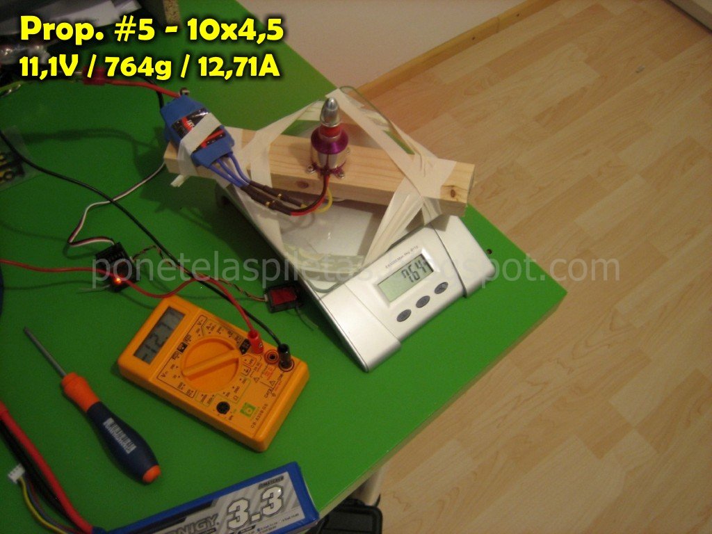
En este post les traigo una información que puede resultar valiosa y útil para los aeromodelistas. Me he tomado el trabajo de realizar una prueba de empuje de las hélices que tenía disponible y documentar los resultados en una tabla, además de tomar fotos.
In this post I bring you some data that can be useful for the aero-modellers. I've done a thrust test of the propellers that I have available at home, documenting the results in a table and taking some pictures.

Las hélices que he testeado son:
The propellers tested are:

#1 - 5x5
#2 - diam 80mm (modif)
#3 - 8x4
#4 - 8x6
#5 - 10x4,5
#6 - 12x4,5


Para la realización de esta prueba he utilzado una báscula electrónica de cocina sobre la cuál he montado una madera que he utilizado de bancada para el motor. Evidentemente, las hélices se han montado de tal manera que el empuje presione la placa de la báscula (la hélice "sopla" hacia arriba).
To carry this test I've used an electronic bascule (those for cooking), in which I've located a piece of wood to give support to the motor. Obviusly, the propellers have been attached in such a way that the thrust generates a pressure on the bascule plate (the propeller blows air upwards).

De momento solo he realizado la prueba utilizando un motor brushless C2830 KV1000 (el que tengo en el quadcopter). Sin embargo, he tomado mediciones utilizando dos tensiones de alimentación diferente: 7,2 y 11,1 Volts (baterias Lipo de 2 y 3 celdas). Si me agarran ganas y tengo tiempo, realizaré la misma prueba pero con otro motor (CF2805-14 KV2840).
By the moment I've done the test using only one motor, a brushless C2830 KV1000 (the one that I'm using in the quadcopter). However, I've taken measurements using two different input voltages: 7,2 and 11,1 Volts (Lipo batteries of 2 and 3 cells). If I feel like and got some time, I'll redo the test for another motor that I have (a CF2805-14 KV2840).

En el montaje del "banco de pruebas" he incluido un multímetro (como amperímetro) para tener la medición de corriente consumida. Todos las hélices se probaron con la misma configuración de motor, esc (60A) y trimado de radio. La balanza fue puesta a cero cada vez antes de iniciar un nuevo test.
In the set-up of the "test bench" I included a multimeter (used as amperimeter) to get the current consumption. All the propellers were tested using the same configuration of motor, esc (60A), and radio trimming. The bascule was set to zero every time before starting a new run.

A continuación les dejo todas las fotos y al final las tablas y unas curvas para representar gráficamente los resultados obtenidos.
I leave you here the pictures and a table with the data collected, as well as some graphs showing the tendences.


Saturday, 31 March 2012

Motor paso a paso 24BYJ01

Stepper motor 24BYJ01

Probablemente se trate del motor paso a paso más común o más fácil de encontrar, ya que lo venden los chinorris por ebay a menos de 3€ con el envío incluido... creo que por tamaño y precio es ideal para empezar a hacer algunas cositas con Arduino o incluso hacer un CNC casero a escala.
Probably this is the most common, known and easy to find stepper motor, because it's sold in ebay and the chinese guys will send it to your address for less than 3€. I think that for size and price is ideal to start doing some funny things with Arduino, or even a small scale home-made CNC machine.


Les dejo aquí los datos técnicos, las dimensiones y el conexionado. Los datos para el motor de 5VC, aunque también se puede conseguir en 12VC. Como se puede ver en la imagen del conexionado, se trata de un motor unipolar.
Here you can find the technical data, dimensions and the wiring. The data sheet is for the 5VDC, but you can also find this motors for 12VDC. As you can see in the wiring diagram, it's an unipolar motor.


  • Rated voltage: 5VDC
  • Number of Phase: 4
  • Speed Variation Ratio: 1/64
  • Stride Angle: 5.625° /64
  • Frequency: 100Hz
  • DC resistance: 50O±7%
  • Idle In-traction Frequency: > 600Hz
  • Idle Out-traction Frequency: > 1000Hz
  • In-traction Torque  >34.3mN.m(120Hz)
  • Self-positioning Torque >34.3mN.m
  • Friction torque: 600-1200 gf.cm
  • Pull in torque: 300 gf.cm
  • Insulated resistance >10MO(500V)
  • Insulated electricity power: 600VAC/1mA/1s 
  • Insulation grade: A 
  • Rise in Temperature <40K(120Hz)
  • Noise <35dB(120Hz,No load,10cm)


Si te interesan los paso-a-paso pero estás medio perdido, te recomiendo que leas el siguiente tutorial: http://www.todorobot.com.ar/informacion/tutorial%20stepper/stepper-tutorial.htm

Sunday, 11 March 2012

Arduino Mega 2560

Compré una placa Arduino Mega 2560 por ebay... 30€ puesta en casa...

¡Cómo cambian los tiempos!

Me acuerdo hace 20 años atrás cuando mi vieja me compró una interface PDK 4.4 para conectar a mi vetusta PC XT por el puerto paralelo (si, el de la impresora)... La había visto en una feria de ciencias y me había fascinado, cuando por aquellos tiempos tenía mis primeras compus y llevaba haciendo un par de años mis circuitos electrónicos...

La PDK tenía 4 entradas y 4 salidas todas analógicas, y se controlaba con BASIC... era muy limitada pero yo fui feliz encendiendo y apagando cositas y leyendo mis 4 entradas on/off con la XT de 640K de RAM... eso si, siempre conectada a la PC, porque no era autónoma (se trataba solamente de una interface, no de un microprocesador).

Ahora por 30€ tenemos todo un microprocesador, y no necesitamos de saber Assembler ni tener 20 circuitos para alimentarlo o programarlo... Arduino, se trata de un proyecto iniciado por unos italianos basado en la filosofía del "código libre". Básicamente es una interface microprocesada (o sea, con cerebro autónomo) con múltiples entradas/salidas digitales y analógicas controladas por el microprocesador ATmega2560 de bajo coste y que puede programarse de una manera muy simple, casi como si de "LOGO" se tratase (los más jóvenes no sabrán ni de qué hablo)...

Por seguir la filosofía "código libre", tanto la el circuito como el software están disponibles gratis para quien lo quiera fabricar o usar por su cuenta. En el caso de la 2560, se trata de una placa con 54 entradas/salidas digitales mas 16 analógicas, con interface USB incorporada.

Veremos qué se nos ocurre con Arduino... de momento, una buena cantidad de piezas de Lego Technic esperan para hacer de "plataforma" al cerebrito...


The Arduino Mega 2560 is a microcontroller board based on the ATmega2560 (datasheet). It has 54 digital input/output pins (of which 14 can be used as PWM outputs), 16 analog inputs, 4 UARTs (hardware serial ports), a 16 MHz crystal oscillator, a USB connection, a power jack, an ICSP header, and a reset button. It contains everything needed to support the microcontroller; simply connect it to a computer with a USB cable or power it with a AC-to-DC adapter or battery to get started.


palabras clave: arduino microprocesador lego technic 
keywords: arduino microprocessor lego technic