Ansmann Racing Mad Rat Front Suspension 3D Printable Arm - .stl .igs .stp CATIA .model
Ansmann Racing Mad Rat Vorderachse Querlenker für 3D-Drucker
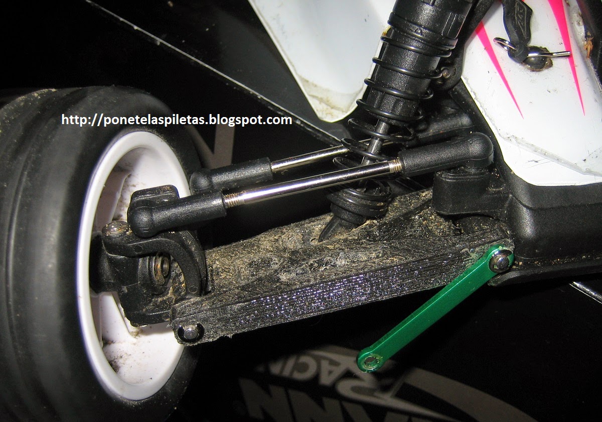
This is my reinforced version of the front suspension arm for the Ansmann Racing Mad Rat RC car.
I designed it taking the main dimensions from the original, but adding
some thickness and material in those areas that shown to be weak to me
(I broke a couple of the original ones in some hard jumps).
This design is a right-hand fully printable version. If you need the
left hand, you just need to mirror this model in your printer sofware or
your CAD.
Integrated FPV system with 7" LCD screen and 3D-printed frame - 1st delivery
Hace ya un tiempo que compre los componentes para poder montar un FPV con los aeromodelos que tengo, o un hipotético renacimiento del quadcopter en el futuro, pero por falta de tiempo, otros proyectos y la falta de una pantalla o unas gafas FPV (googles) había dejado el proyecto en stand-by hasta ahora.
It's been a while that I've bought some components for building up my FPV system to be mounted in my planes or a future re-born of the quadcopter but due to a lack of time, other projects and the missing screen or googles to view the transmission the project was in stand-by.
El problema era que no estaba seguro de invertir 300€ en los googles sin tener claro si luego realmente les iba a sacar partido, así que me decidí por comprar una pantalla LCD de 7" en ebay que me costó menos de 40€ incluyendo la placa controladora con entrada para AV, VGA y HDMI.
As I was not sure if investing almost 300€ in the googles was going to make sense, I just decided to go for a 7" LCD screen that I've bougth in ebay for less than 40€, including the controller board (with AV, VGA and HDMI inputs).
Pero lo siguiente era poner todos los componentes juntos, así que diseñé un pequeño marco para imprimirlo con la impresora 3D que me sirviera para acomodar los componentes de una manera compacta, y en un futuro tal vez poder montar el conjunto sobre la radio RC o en un trípode.
But now I needed to put everything together, so I designed a 3D-printed frame to arrange the componentes with the idea of keeping the system compact (and maybe later on mount this directly on top of the RC radio).
GoPro Hero 3 mount for Axial Dingo
Se trata de un soporte para la cámara GoPro Hero3 para poder montarla arriba del crawler Axial Dingo, mas precisamente en la barra antivuelco, aunque también puede usarse para otras aplicaciones.
This is a very
simple mount for the GoPro Hero 3 camera designed to be position in the
Axial Dingo roll cage, but it can also be used in other applications.
Prusa i3 by diegudio - Hot-end heat dissipator
Después de probar con diferentes configuraciones de hot-ends, incluyendo el que he fabricado yo mismo usando una barra roscada de bronce y alambre de Ni-Chrome, creo que estoy en condiciones de compartir con ustedes lo que (espero) sea mi configuración definitiva.
After doing several trials with different hot-end configurations, including the one that I've made myself usign a bronze bolted bar and Ni-Chrome wire, I think I'm in position of sharing my (hopefully) definitive configuration.
El hot-end que se puede ver en la imagen de arriba me dió satisfacciones por el hecho de haberlo hecho yo mismo, pero también me dió muchos dolores de cabeza porque al enrollar el Ni-Chrome directamente sobre la cinta Kapton esta última se quemaba muy fácilmente y cada tanto había que desarmar todo y volverlo a armar. Tampoco era un buen montaje para el termistor, ya que el mismo quedaba apoyado directamente sobre la kapton, y el montaje no era muy firme, lo que generaba oscilaciones de la medición. Finalmente, el diámetro de extrusión tampoco era ideal, ya que al haberlo hecho con una broca de 0.5 manualmente, el agujero seguramente tendría un diámetro algunas centésimas mayor, por lo que el filamento extruído era algo mas grueso.
The original bronze-Ni-Chrome hotend (see picture above) was giving me too many problems, although the printing quality was considerably good for being self-made with just a hand drill (no special tools). The assembly was not so stable, the Kapton tape was burning due to the direct contact with the Ni-Chrome and it was not lasting too long, the thermistor connection was also unstable and I was having an annoying temperature fluctuation, and last but not least, the diameter of the extruder filament was a little big (perhaps doing the hole manually with normal tools was giving a higher diameter than the expected).
Así que me decidí a comprar algunos componentes pre-fabricados para mejorar el hot-end, que como todos sabemos es la parte más sensible de las impresoras 3D. Compré una resistencia de cartucho, termistores encapsulados (que aguantan +300ºC teóricamente), el bloque de aluminio donde se monta todo y el cuerpo roscado para filamento de 1.75mm que es lo que tengo en casa. También compré el cabezal extrusor roscado, por si luego quiero experimentar con diámetros mas pequeños.
So I bought some components to start improving my work. I bought the heating cartridge, some more thermistors (the transparent ones, up to +300º), the aluminum heater block and the main body for 1.75mm filament, with an exchangeable head with 0.5mm hole (exchangeable so that in the future I can try smaller holes).
Sin embargo, no quería comprar absolutamente todo, incluyendo los aisladores de PEEK o PTFE, principalmente porque si lo compramos todo hecho, dónde está la gracia no???... Tampoco estaba seguro de que comprando un aislador pre-fabricado me fuese a encajar bien en mi extruder.
However, I didn't want to buy the whole stuff, including the PEEK or the PTFE isolators, mostly because if I bought everything then where is the fun?? I was not sure that with the typical cilindrical isolator I was going to be able to attach the hot-end to the extruder.
Así que la razón de este post es enseñarles cómo resolví el montaje y al mismo tiempo el problema de disipación de calor.
So the reason of this topic is to show you how I solved the mounting issue and at the same time, the most important thermal dissipation issue.
This is a very simple clip that I've designed for holding a piece of glass or a mirror to the hot (heated) bed of your reprap 3D printer.
I've uploaded the files in .stl .igs .stp and also the original made in CATIA v5R21 to Thingiverse, just follow the link to dowload:
http://www.thingiverse.com/thing:240181
The original design has a clearance of 5mm with a arm length of around 15mm.


