PRUSA i3 by diegudio - 2nd Delivery - Building details Les dejo algunas fotos de la evolución de la construcción de mi Prusa i3. En general casi todo se puede hacer siguiendo otras impresoras, pero sí que he tenido que hacer algunas modificaciones, ya sea para solucionar problemas que aparecían o a modo de mejoras. I leave you here some pictures of the evolution of the construction of my Prusa i3. In general, almost everything can be done just following other construction blogs, but I do needed to implement some modifications, either to solve some problems that were appearing, or just as improvements. Por ejemplo, el corte que tiene el marco principal en la
zona central para que pase la correa del eje Y tuve que agrandarlo
porque no solo tocaba la correa con la madera sino que tampoco pasaba el
soporte que fija la correa a la mesa (2a y 3a foto). For example, the cut in the main frame at the central location to allow the belt of the Y axis to go through was not big enough as both the belt and the belt fixation were clashing (2nd & 3rd picture).
Como mencioné en el último post relacionado con la impresora 3D, voy a poner en stand-by el proyecto "diegudios" dados los problemas que encontré en el desplazamiento de los carros horizontales. Así que mientras que se me ocurre cómo solucionarlo, he decidido montar una Prusa i3 (iteración 3) para lo cuál me he comprado las partes impresas por ebay. As I mentioned in the last post related to the 3D Printer, I'll put in stand-by the "diegudios" conceptual printer because of finding some issues with the sliding of the horizontal carts. So I've decided to spend some time building a Prusa i3 frame with printed parts bought in ebay. Lo bueno de la Prusa i3 es la reducida cantidad de piezas que tiene el concepto, si se lo compara con otras impresoras. Por si esto no fuera suficiente, se consigue un marco muy fácil de armar con una rigidez estructural correcta. The good thing of the Prusa i3 is the reduced amount of parts that the concept has, compared to other concepts. As a result you can get a very easy-to-assemble frame with a good structural stability.
prusa i3 frame dimensions and CATIA 3D model for DIY He subido a thingiverse un drawing con las dimensiones del marco de la prusa i3 para aquellos que prefieran fabricarlo en vez de comprarlo. También podrán encontrar en el link un modelo CATIA v5R18 3D (CATPart) y su conversión a .igs y .stp. I uploaded to thingiverse a drawing with the dimensions of the prusa i3 frame for those of you who prefer to do it yourself, including also a CATIA v5R18 3D model (CATPart) and some .igs and .stp files.
Los datos después del salto // The link after the jump
DIEGUDIOS - Impresora 3D RepStrap - 5th delivery Después de varias pruebas fallidas he decidido cambiar la configuración de la mesa X-Y de la impresora. Estos fallos se debieron principalmente a que el desplazamiento del carro Y lo realizaba con la correa descentrada de las guías (por fuera de estas digamos) y esto inducía un momento sobre los patines de las guías que no era bien recibido por estas. En otras palabras, este momento en el plano generado por la desalineación de la correa con la guía generaba una resistencia al avance del carro, y hacía imposible moverlo con el NEMA17. Supongo que partiendo las guías en dos partes y separando cada barra (separando los patines) se ganaría una mejora en "capacidad de absorber momento", pero entonces tal vez ya no sería necesario porque habría sitio para meter la correa por entremedio de las guías (y el diseño tipo L de mi impresora ya no valdría mas). After several failed tests I've decided to change the configuration of the X-Y table. The tests were failing because with the igus guides the motors should push/pull from the center of the guide, if not, they will induce a moment in that will add some resistance to the advance of table. In other words, the igus guides doesn't like so much to handle the advance and also an in-plane moment (at least no in this configuration, but I guess that if I split the guide in two pieces to separate the skids, then the in-plane moment could be handled better, but at the same time the separation of the guides will give some space extra to put the belt in between them)...
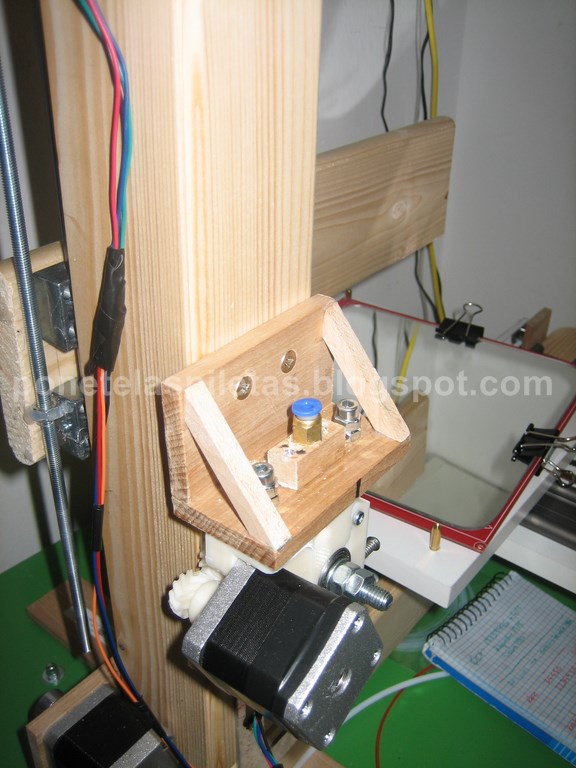
Así que he decidido mover el eje Y al brazo donde antes tenía solo el extruder. Y seguramente a estas alturas te estarás preguntando si eso no sería trasladar el problema al eje Z; pues la respuesta es no, porque el eje Z al ser movido por el tornillo (husillo) tiene mucho mas poder de empuje y entonce el NEMA17 es suficiente para manejar el extra de resistencia al avance que se genera por tener todo el peso de la guía Y, el motor Y y el extruder "colgando" del brazo. So, I decided to move the Y axis to the arm where I use to have the extruder. You will be wondering: but this will shift the problem to the Z displacement?... actually, not, because the Z cart is driven by the threaded bar (spindle), and the spindle has much more pushing/pulling power than the belts, so it can handle perfecly the extra resistance to the advance of the Z cart due to the in-plane moment generated by the Y-axis, the Y-axis motor and the extruder hanging from the arm. Finalmente el problema del avance del eje Y fue solucionado, al menos en lo que al momento respecta, y ya estaba en condiciones de realizar mi primera impresión, que, por supuesto, no fue satisfactoria (¿¿¿alguna vez alguien imprimió de primeras sin problemas???); las correas pareciera que no están suficientemente tensionadas y algunos pasos del desplazamiento X-Y se saltan, y también tengo problemas con el eje Z porque la tuerca del husillo está fijada de muy mala manera y se mueve. Finally, the problem of the advance of the Y-axis is solved, and I was able to do my first printing test, but I'm afraid it was not satisfactory (did anybody have a first satisfatory printing???); the belts are not tightened enough and I have some jumps on the X-Y displacement, and the Z axis is also unstable because the spindle is captured by a nut that is well supported (yet).
Multiplex EasyStar with GoPro Hero3 White Edition flying in Upper Austria Primer vuelo con la GoPro Hero3 White Edition montada en mi avión EasyStar de Multiplex, volando sobre un campito en Hohenzell, cerca de Ried im Innkreis en la región de Alta Austria (si, obviamente, en Austria). First flight with the GoPro Hero3 White Edtion mounted in my EasyStar from Multiplex, fliying over a field in Hohenzell, close to Ried im Innkreis, in the region of Upper Austria (naturally, in Austria)... He mejorado un poco como piloto gracias a un simulador que tengo en el ordenador, pero todavía necesito mas vuelos... no obstante, ya hecho en falta los alerones para lograr un vuelo mas controlado. Supongo que seráel próximo upgrade del EasyStar. My skills as pilot have improved a little bit thanks to the PC simulator, but I still need more flights... however, I'm already missing the ailerons for a more controlled flight... I guess that they will be the next upgrade of the EasyStar...
Por cierto, en el video se pueden ver un par de loopings, mis primeros loopings... By the way, in the video you can see my first partially-controlled loopings...
extra keywords: fliegen flugzeuge Oberösterreich Österreich modellbau
DIEGUDIOS - 3D Printer - Opto endstops with HY860H Mucha información hay en la web y en reprap.org acerca de los "sensores de final de recorrido", endstops en inglés, y sus derivados (mecánicos, ópticos), así que no es mi intención explicar para qué sirven. Lo que aquí les traigo es información de cómo hacer sus propios opto endstops con la barrera óptica HY860H-A que se consigue por ebay a precios muy económicos (10 x 1,53€ envío incluído). There is a lot of information in the web and reprap.org about the endstops and their derivatives (mechanicals, opticals), so it's not my intention with this post to explain why you need them. I'm just bringing you here infromation of how to do your own endstops using the optical barrier HY860H-A which is extremely cheap and you can buy 10 of these in ebay for 1,53€ including shipping. No se olviden que este componente tiene el emisor (del foto-transistor) del lado contrario al ánodo del LED infrarrojo, por lo tanto si usan el circuito que les dejo mas abajo, tienen que tener cuidado de conectarlo adecuadamente (la masa iría cruzando el encapsulado de un lado al otro). Notice that this opto-barrier has the emisor on the opposite side of the IR-LED anode, so in the circuit that you will see below, you need to be careful of taking the emisor properly (ground will cross from one side to the other).
Mas allá de esta particularidad constructiva, el HY 860H se puede usar con cualquiera de los circuitos típicos que se pueden encontrar en la web. Yo prefería tener un LED como referencia visual para saber si estaba funcionando el circuito correctamente y he utilizado el diagrama que se puede ver en el blog Capolight Electronics Projects. Besides this particularity, the HY 860H can be used with any of the tipical circuits that you can find in the web. I preferred to have a LED as a visual reference of the state of the endstop so I used the circuit presented in the blog Capolight Electronics Projects.
Se puede realizar otra disposición del LED y su resistencia para que en vez de estar normalmente encendido solamente se encienda cuando la barrera es activada. Para ello hay que colocarlo tomando su positivo del emisor del foto-transistor y conectando la resistencia a masa. El resto se mantiene igual. You can also use a diferent set-up of the LED so instead of having it normally on it goes to "on" when the barrier is activated. For this you need to take the signal from the emisor of the photo-transistor and conect the anode of the LED there, and the cathode goes through the 560ohm resistor to ground. The rest of the circuit remains the same. Para finalizar, les dejo las hojas de datos del HY860H y unas fotos de cómo quedaron mis plaquetitas. To finish, I leave you here the HY860H datasheets and some pictures of my boards.
DIEGUDIOS - 3D RepStrap Printer - 4th delivery Aquí les traigo mas fotos del avance de mi impresora 3D tipo RepRap (RepStrap). Como pueden ver en las fotos, falta muy poco para la finalización. También pueden ver que he fabricado mi propio hotend, pero ya luego les daré mas detalles de eso en un próximo post. I bring you here more pictures of the advance of my RepRap (repstrap) printer project. As can be seen, I've advanced quite a lot in the assembly. You can also see that I've created my own hotend, but I will come back with the details in another post.


.JPG)


.JPG)
.JPG)


.JPG)


.JPG)
.JPG)


.JPG)

.JPG)